Timing software setup
Connecting to the network
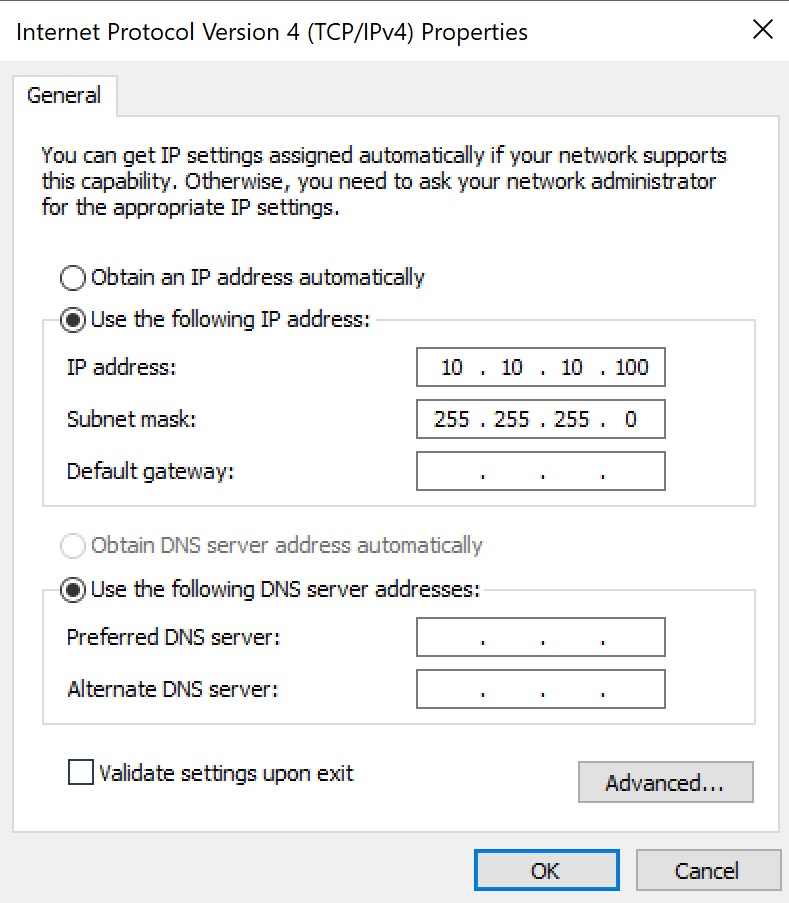
Make sure both the Timing computer and the Graphics server are connected to the network with the timing devices using ethernet. Both computers should have an IP address in the 10.10.10.XXX range. They cannot conflict with each other or with the timing devices.
Best practices for IP addresses:
Device |
Address |
10.10.10.100 |
|
10.10.10.101 |
|
10.10.10.102 |
|
Displays Moxa Nport |
10.10.10.103 |
Videotiming computer |
10.10.10.150 |
10.10.10.200 |
Example, the Timing computer should look like:
Setting up the timing manager
The software remembers its settings, so only on new Timing computer installations these settings should be set.
The settings are also saved in Documents/Stihl Timbersports/Settings/Settings.xml. The software window layout (i.e. how the software looks) is stored in Documents/Stihl Timbersports/Settings/WindowLayout.xml. It is good practice to backup these files.
To connect to the STIHL Timbersports Datahub, set your credentials in the Settings tab, DataHub section.
Connecting to the timing device
The settings to connect to the Timing device are located in the Timing manager. They can be found in the Settings tab under Timing. The software remembers its settings, so only on new Timing computer installations these settings should be set.
To connect to the Timing device, follow these steps:
In the settings tab:
Expand the TimingTimySettings group
Set the layer to TcpClient
Expand the TcpClient group
Expand the ServerAddress group
Set Hostname to the Timing device IP address (usually 10.10.10.101)
Set Port to the Timing device IP port (usually 4001)
Restart the software.
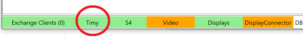
After setting up the connection to the Timing device, the Timy field in the status bar should be green like the image below.
Connecting to the start box
The start box contains a external sound card which interfaces with the computer over USB. For the start signal to trigger, Windows should be set up to use this external sound card. This can be done in Windows 10 by opening Settings > System > Sound and setting the output device to Radial pro or similar.
The volume should be set to 100%.
The latest Starting cadence audio file can be downloaded from the STIHL Timbersports Datahub. This file should be stored on the computer. Best practice for this is in the folder Documents/Stihl Timbersports/Start cadence.
Configure the Timing manager to use this file:
In the settings tab, in the Timing section:
Under AudioFilePath, enter the full path to the audio file.
Note: By clicking AudioFilePath a button with three dots appears in the field. Clicking this button opens a file navigator helper.
Standchannel mapping
The Standchannel mapping is responsible for mapping impulse ports on the Timing device to the right stand. Without this mapping, the software doesn’t know which button belongs to which channel.
Setting up the mapping:
In the Timing manager, go to Settings > StandChannelMappingTimy and open it.
Note: There are 2 properties with similar names. Make sure to open the StandChannelMappingTimy
Set the mapping as shown below:
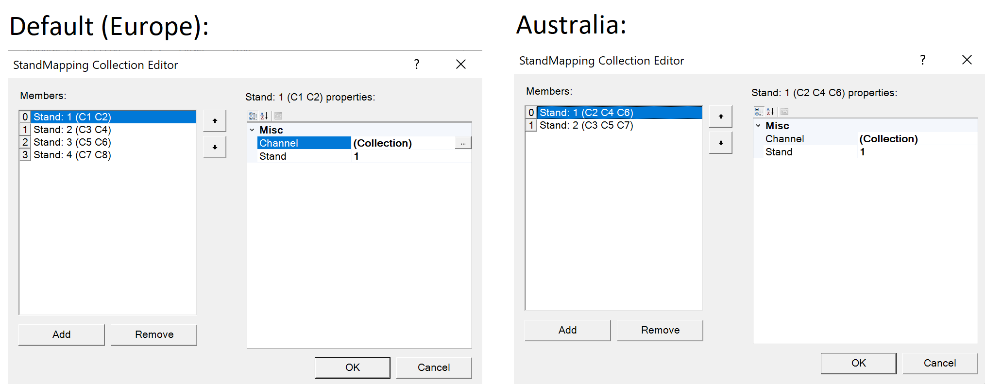
Set StartChannelTimy to C0
Connecting to the displays
To connect to the displays, open the Display connector software. The software remembers its settings, so only on new Timing computer installations these settings should be set. The settings are also saved in Documents/StihlTimbersportsDisplayConnector/Settings.xml, it is good practice to backup these files.
To connect to the displays:
open File>Settings.
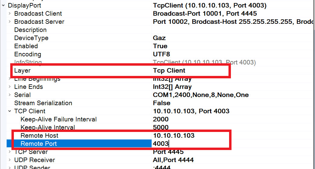
under Displayport, set the layer property to TCP Client
under Displayport>`TCP Client` set the ‘Remote host` property to the ip address of the display Moxa Nport. Usually 10.10.10.103.
under Displayport>`TCP Client` set the ‘Remote port` property to the port of the display Moxa Nport. Usually 4003.
Restart the Display connector software
After restarting the display connector software, the Display status in the bottom toolbar should be green. If it is not, double check the connection to the Moxa Nport over ethernet and the IP address.
Setting up the displays
Each display has its own unique address. We have to map the right stand to the displays. Follow these steps:
open File>Settings.
Click the Dlinemapping property, and then on the button with the 3 dots behind it
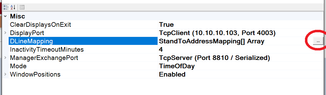
There should be at least as many members in the left list as there are displays. Having more is no problem. If there are not enough members, add them using the button at the bottom.
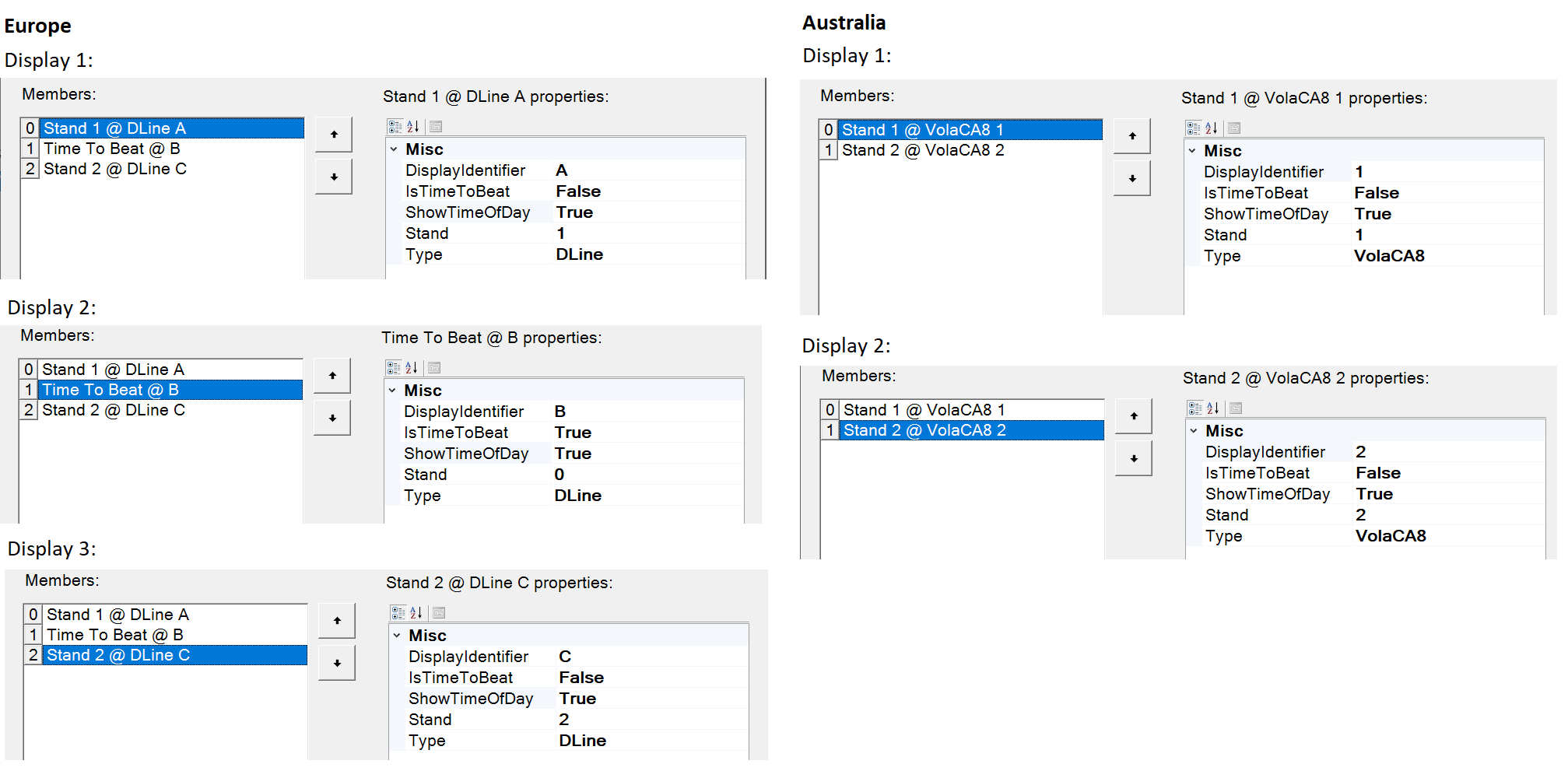
For every display, configure the following by selecting a member on the left:
DisplayIdentifier: the unique ID programmed into the display.
For Alge Dline displays (Europe): a letter A, B, C, D, E or F.
For Vola CA8 displays (Australia): a number 1, 2, 3, 4, 5, 6, 7 or 8.
IsTimeToBeat: if True, this display only shows the time to beat. If false, it shows the time of a stand
ShowTimeOfDay: if True, this display will show the time of day when this is selected as display mode, otherwise blank
Stand: The stand number. This refers to the StandChannel in the timing manager, it is 1, 2, 3 or 4. 1 is most left, 4 is most right. For an A / B stand setup, 1 is stand A, 2 is stand B.
Type:
For Alge Dline displays (Europe): Dline
For Vola CA8 displays (Australia): VolaCA8
Press ok, close the settings
After closing the settings, the display connector shows the signals send to the displays if they are connected.
Default settings are:
Setting up live results
The liveresults connector has to be configured to connect to the right server. Follow these steps:
open File>Settings.
Click the LiveResultsHost property, and then on the button with the 3 dots behind it

Make sure there is exactly one member, which has Enabled = True and Url=https://live.stihl-timbersports.com
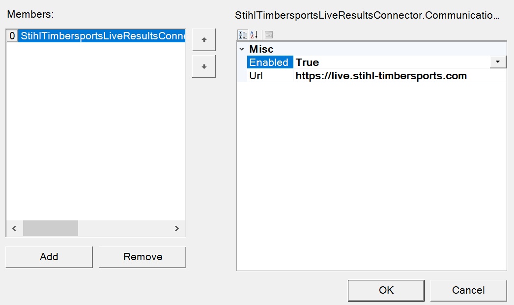
Press ok, close the settings
Restart the liveresults connector
Note: the liveresults connector only connects when a Timing manager instance is running, with an open database which has a non empty Live event id.
Printout headers
For printouts (starting orders / results), the header and footer images should be the following:
All National competitions and national championships
Header: Centered Stihl Timbersports logo
Footer: Blank
World Trophy
Header: Centered Stihl Timbersports logo
Footer: Liebherr, Volkswagen (big), Jacques Lemans
World championships
Header: Centered Stihl Timbersports logo
Footer: Volkswagen, Liebherr (big), Jacques Lemans
All time schedules
Header: Centered Stihl Timbersports logo
Footer: Blank
The location of the header and footer files can be set:
In the Timing manager settings tab:
Go to the printing section
Set the LandscapeFooterLogoPath, LandscapeHeaderLogoPath, PortraitFooterLogoPath, PortraitHeaderLogoPath to the right images.