Graphics setup
Configuring CasparCG Server
The CasparCG server has many configuration options, which are defined in its configuration file. We do not use many of these parameters and it is discouraged to change anything in this file except for the options mentioned below.
See Directory Structure to see where the configuration file is located.
The basic configuration file looks like this:
<?xml version="1.0" encoding="utf-8"?>
<configuration>
  <paths>
    <media-path>media/</media-path>
    <log-path>log/</log-path>
    <data-path>data/</data-path>
    <template-path>template/</template-path>
    <thumbnail-path>thumbnail/</thumbnail-path>
    <font-path>font/</font-path>
  </paths>
  <html>
    <enable-gpu>true</enable-gpu>
  </html>
  <lock-clear-phrase>secret</lock-clear-phrase>
  <channels>
    <channel>
      <video-mode>1080i5000</video-mode>
      <channel-layout>stereo</channel-layout>
      <consumers>
        <decklink>
          <device>1</device>
          <latency>low</latency>
          <keyer>external</keyer>
        </decklink>
        <screen>
          <device>1</device>
          <windowed>true</windowed>
        </screen>
        <system-audio></system-audio>
      </consumers>
    </channel>
  </channels>
  <controllers>
    <tcp>
      <port>5250</port>
      <protocol>AMCP</protocol>
    </tcp>
    <tcp>
      <port>3250</port>
      <protocol>LOG</protocol>
    </tcp>
  </controllers>
</configuration>
Output format
Most of these settings should not be changed. However, the consumers block might be of interest, as this defines the different outputs of the server.
In the default configuration, we see 2 consumers: decklink and screen.
The decklink consumer holds the configuration for the Decklink SDI output, which is the output used for the video production.
In the basic example, the server is configured to send the video signal to the first decklink device (see the Blackmagic Desktop Video Setup software to see which device this is).
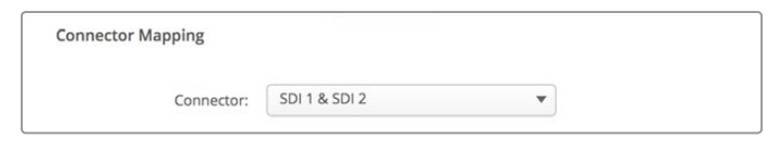
The keyer is external, meaning a separate fill and key output output are used.
This only works when the output is setup to use 2 connectors, see the image below.
The screen consumer is also setup by default for debugging purposes. However, this should be disables during the event by removing
<screen>
  <device>1</device>
  <windowed>true</windowed>
</screen>
from the configuration file and restarting the server, as the screen consumer impacts performance.
Output resolution
The resolution is also set in the CasparCG config file, see the video-mode configuration option. Available configuration options are:
PAL
NTSC
576p2500
720p2398
720p2400
720p2500
720p2997
720p3000
720p5000
720p5994
720p6000
1080p2398
1080p2400
1080p2500
1080p2997
1080p3000
1080p5000
1080i5000
1080p5994
1080i5994
1080p6000
1080i6000
The video service provider knows which resolution they want to use.
Graphics client setup
The settings in the Graphics client are found in the Menu bar.
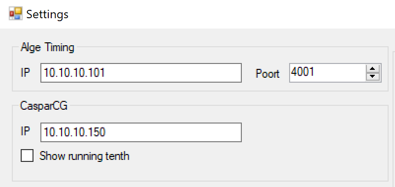
In the Alge Timing IP field, enter the IP address of the Timing device.
In the CasparCG IP field, enter the IP address of the Graphics server.
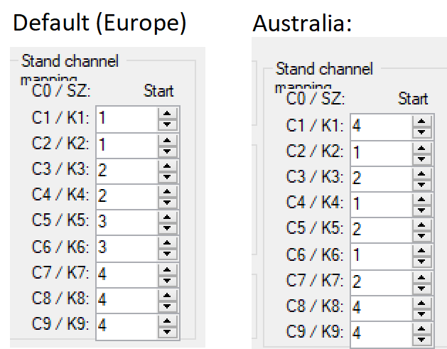
The Graphics client also needs to be aware of the Stand channel mapping. Set to the following: